
|
Fig. 1
The DR111 is neat and small
|
|
The Newstar DR111 arrived here by the Swiss Post via FedEx, well packed
in a DHL plastic bag and in good condition. I paid USD 120.- for the
radio and USD 45.- for the transportation from Hong-Kong. On top of
that FedEx presented a bill where they charged me a total of EUR 27.41
in VAT, their handling and import duty - 1.5 kg from China cost EUR
0.71!
The DR111 is 275mm wide, 90 mm deep, 115 mm high and weighs 825 gram.
The controls are rather self-explanatory and you soon get used to the
operation. The only draw-back is that the clocking of the pushbuttons
seem to be a bit on the slow side, so one needs to pause when pushing
the same button repeatedly (when setting the frequency). It would have
been nice to have an oldfashioned volume control instead of the step
function. Especially the step from the first to the second level could
have been divided into three, as the increase in volume is too much.
Especially if you are using the DR111 on a bedside table you feel the
difference.
The telescopic antenna is used mainly (?) for the Short Wave and FM
reception. For Long- and Medium Wave there are two separate Ferrite
Antennas built into the set. An AC/DC Power Supply with 5 Volt output is
used to run the DR111 off the Mains. There are no built-in batteries in
the radio, so it cannot used as a portable set.
It has now been playing DRM fairly well for a while, both on medium- and
on short-wave. However, the scan function on DRM leaves a lot to wish
for as you'll be lucky if it stops on a DRM TX at all. Mind you, this
morning it did stop on BBC on 7355 kHz and yesterday it managed
to halt on REE on 13720 kHz. Just for my curiosity, I pressed scan half
an hour into the TDP transmission on 6015 kHz and during the last 30
minutes the DR111 did NOT stop again before the transmission was over -
despite a solid RF signal here 470 km away from the TX.
|
|
SOME MEASUREMENTS ON RECEPTION AND AUDIO QUALITY
|
Receiver sensitivity on AM.
|
The sensitivity was measured by connecting a signal generator to the
External Antenna connector. The signal Generator was set to 60% AM
modulation and the level was adjusted for 20 dB SINAD reading. The
sensitivity of the DR111 in AM mode is very good over the entire AM
tuning range.
|
|

|
Fig. 2
|
The S-Meter behaviour from 150 kHz to 27 MHz
|
The graph below shows the RF Input Level in µV which is needed to light up 1 segment and 3 segments in the S-Meter display.
|
|

|
Fig. 3
|
Volume Control Characteristics
|
The volume control is not continous, but consists of 17 steps where the
Step 0 is quiet. The last steps down to zero show an abrupt decrease in
the speaker output. It would have been better to have smoother steps
at low levels and the larger steps towards maximum volume.
|
|

|
Fig. 4
|
A close-up plot of the last four steps of the volume control shows the
steep fall towards zero volume. It would have been better to have had a
smoother ending.
In the meantime the manufacturer told me on 1st June2012 that they will adjust this issue in the next firmware release.
|
|

|
Fig. 5
|
|
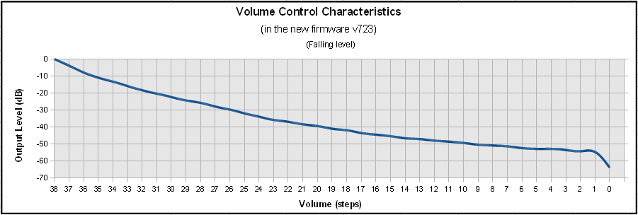
The volume control in the latest firmware version 723 from July 2012 has
been changed from 17 to 39 steps. The result is much better than in
the previous version. Now you can put it on the bed-side table an turn
the volume down very low.
|
|
|
Fig. 6
|
AM Adjacent Channel Selectivity
|
The Selectivity was measured at 11830 kHz with 50 µV RF Input level in
50 Ohm and modulated with 1000 Hz, 60% AM. The signal generator was
adjusted in 1 kHz steps up and down from the receiver frequency and the
AF output was measured in dB relative to the center frequency. Three
measurements were done with 1 kHz (yellow), 5 kHz (red) and 6 kHz (blue)
kHz IF bandwidth.
|
|
|
Fig. 7
|
Unwanted spurious response on AM
|
The signal generator was tuned to 20000 kHz and its output level was
adjusted to +80, +60 and +55 dBuV respectively. An AM scan was
performed for each input level. On 21640 kHz a tone was heard in the
loudspeaker. On the other frequencies listed below the DR111 stopped
scanning, but nothing was heard in the speaker. There are no data
available for IF frequency and no information on whether the receiver is
a single or double conversion superheterodyne. The results are shown in
the table below:
|
|
Unwanted +80 dBµV
|
Unwanted +60 dBµV
|
Unwanted +55 dBµV
|
Notes
|
|
6000 kHz
|
|
|
|
|
9520 kHz
|
|
|
|
|
9775 kHz
|
|
|
|
|
15200 kHz
|
15200 kHz
|
|
|
|
19100 kHz
|
19100 kHz
|
|
|
|
21640 kHz
|
21640 kHz
|
21640 kHz
|
Sine wave
|
|
25640 kHz
|
25640 kHz
|
25640 kHz
|
Question mark
|
|
26000 kHz
|
26000 kHz
|
26000 kHz
|
Question mark
|
|
Fig. 8
|
Automatic Gain Control in AM Mode
|
The graph below was plotted at 1296 kHz on Medium Wave. An abrupt
increase in the RF input level causes the DR111 to reduce (IF?) gain in
steps. This can be heard in the loudspeaker. The audio output in the
speakers is fairly constant at RF levels above 1.5 µV. Below 1.5 µV the
audio output decreases rapidly. There is no noise att all in the
loudspeakers in absence of a signal or at very low RF signal levels.
|
 |
Fig. 9
|
|
AM Audio Response
|
The Audio Response was measured by setting the signal generator to 60%
AM modulation and the modulation frequency was measured from 100 Hz to
6000 Hz. Two series of measurements were done, one with 6 kHz IF
bandwidth (blue curve) and the second with 4 kHz IF bandwidth (red
curve). The result is shown in the graph below.
|
|
|
Fig. 10
|
FM Audio Response
|
In a previous test (with the Morphy Richards radio) I took my old ITT
Schaub Lorenz Touring T60 from the 1960's as a reference receiver. The
Schaub Lorenz sounds very pleasant on FM. I compared this radio with
the AF output from the DR111. The audio frequency response in the Schaub
Lorenz is rather linear from 100 Hz to around 20 kHz. Doing the same
test with the DR111 shows a better audio frequency response compared to
the Morphy but it could be better. Above 4000 Hz the Newstar DR111 has
a roll-off of 20 dB / octave which leaves little output of the higher
frequencies. Still, when listening to an FM station, the sound is not
that bad anyway.
|

|
Fig. 11
|
|
The Audio Frequency response in DRM mode
|
The Dream Software can operate as a DRM Transmitter. This, in connection
with my signal generator Schlumberger Stabilock 4040 created a DRM
Short Wave Transmitter, that was at least good enough for testing the
DR111. I tuned the signal Generator to 7988 kHz. The generator was
modulated in AM mode with the output from Dream set to TX Mode B,
16-QAM / 64-QAM, Protection level 1 und Long Interleaving. The
modulation level was around 35%. In this configuration the DR111
frequency response was about +5 dB/octave linear from 1000 Hz to 6000
Hz. Above 6.2 kHz is practically nothing recordable. This is most
likely a limit due to the Dream TX configuration.
Looking at the output from the signal generator on a HP Spectrum
Analyzer the sidebands with the DRM 12 kHz were clearly visible. The
DR111 was tuned to 8000 kHz. The output level from the signal generator
was set to -47 dBm (1 mV in 50 Ohm).
I made the measurements in the Earphone output jack (3.5 mm Jack). The
result was positive. The frequency response is not linear. But the
reception of DRM signals is still loud and clear.
|

|
Fig. 12
|
|
Power Consumption with the 5 Volt DC adapter (original design)
|
|
State
|
Current
|
Power
|
Notes
|
|
Switched on
|
340 mA
|
1.87 Watt
|
Backlighting ON
|
|
Switched on
|
330 mA
|
1.82 Watt
|
Backlighting OFF
|
|
Stand-By
|
310 mA
|
1.71 Watt
|
|
|
|
Fig. 13
|
|
The DANGER of connecting anything else than the 5 Volt DC Power Supply!
|
|
After an accidental 12 V DC input to the DC jack on DR111 it instantly
short-circuited and died a sudden death. Nothing to do but to destroy
the guarantee seal and remove 8 screws and open the radio to find out
what had happened. A diode marked on the PCB as "ZD1" or "201" had
broken down - it seems this was a Zener Diode connected in parallel to
the DC socket. This explains why the current rose dramatically during
tests with a regulated DC Power supply when the supply voltage was
adjusted slightly over 5.5 V DC. DANGER!!
|

Fig. 14
|
|
I removed the DC socket from the printed circuit board, bent its PLUS
solder lug upwards so it was not in contact with the input voltage
connection any longer and soldered the DC jack back onto the DR111
printed circuit board. In the hole where the 5 Volt lug was connected
before I wired a piece of yellow lead wire to connect to the output of a
7805 voltage regulator. Then I soldered a short red wire to the plus
lug on the DC jack and put a shrink tube over the solder joint to
prevent a short-circuit to ground. There is not much space between the
DC jack and the shield case containing the radio parts.
Next I soldered the 7805 three-pin regulator to the shield case near the
DC jack and wired a 4.7 µF/25V on the input pin to ground and a 22
µF/16V on the output pin to ground. Finally the red wire was soldered to
the input pin of the 7805 and the yellow wire was soldered to its
output. The DR111 now needs an AC/DC Mains Adapter with an output of at
least 9 V (minimum current capacity of 0.5 A) instead of the original
adapter's 5 V DC. The power supply must be capable of delivering at
least 500 mA, otherwise the DR111 might re-boot during power up.
Interestingly, after this modifiaction, the total power consumption of
the radio became lower than before.
|
Power Consumption with the modified DC input
|
|
State
|
Current
|
Power
|
Notes
|
|
Switched on
|
250 mA
|
1.25 Watt
|
Backlighting ON
|
|
Switched on
|
240 mA
|
1.25 Watt
|
Backlighting OFF
|
|
Stand-By
|
195 mA
|
0.98 Watt
|
|
|
Fig. 15
|
|
I don't understand why Chengdu Newstar used the "Stand-By" function as
an ON/OFF switch. When the DR111 is "switched off" it consumes almost
as much power as if it is switched on. It would have been better to
provide a switch on the set that cuts the power supply entirely. After
all we want to save energy. True, when a main swicth is used, the DR111
needs to boot up, but that doesn't take that long anyway.
|
The reception with the Telescopic antenna compared to an External Antenna
|
The sensitivity in AM Mode measured with a signal generator (I can only
measure sensitivity on AM) is in fact not that bad - at least if you
look at Fig. 2 a bit up on this page. But with no documentation or
schematics available, it is hard to say why the performance on the
telescopic antenna - to my liking - is a bit weak. When I switched to
my roof-top active antenna I got much better reception.
Before I connected anything to the external antenna jack I checked if it
was resistive or not. It was. I checked the value, and it was about 1.4
Mohms. Therfore I am feeding the active antenna to the DR111 with a
capacitor in series, not to let any 12 Volts DC from the antenna's coax
cable into the front end of the DR111.
I recorded some data for 9780 kHz (REE) on the internal telescopic
antenna and on my modified PA0RDT active antenna. I got one to two
S-Meter segments lighting (in AM mode) on the internal antenna with
19-21 dB SNR on DRM, compared to 3-4 S-Meter segments (in AM mode) with
the active antenna with 24-25 dB SNR on DRM. That is a >20 dB (factor
>100 at least) difference. The REE signal is pretty strong here in
Switzerland - about 0.6-1 mV / 50 Ohm. On the FRG-7700 the SNR was
around 27-28 dB.
A little later on 9850 kHz (RUVR) I got more or less only 0 (zero)
S-Meter segments (not) lighting (in AM mode) on the internal antenna
with 21-22 dB SNR on DRM, compared to a steady 2 S-Meter segments (in AM
mode) with the active antenna with 25-26 dB SNR on DRM. That is a
considerable difference too. The RUVR signal was not so strong - about
0.1 - 0.11 mV / 50 Ohm. On the FRG-7700 the SNR was around 30 dB.
I did another test with the DR111 connected to two signal generators,
one on 6175 kHz and the other on 7545 kHz. With a -50 dBm signal from
both I got an audible, rather strong signal on f1 + f2 = 13720 kHz in
the DR111. -50 dBm is about 0.7 mV in 50 Ohms. It is hard to say whether
this could be a problem in DRM if there are strong stations on
unfortunate frequencies which adds or subtracts interfere with the DRM
frequency.
|
Tuning the bands and reception results
|
Since the new firmware V790 was published in the beginning of August
2012, the DR111 became much more pleasant to use. The muting of the AF
when tuning either with the tuning knob or with the up/down buttons was
removed. Now you can tune the bands in AM and FM and hear what you are
tuning into. I got another DR111 so I can compare the performance
between the two, and I found out that the second receiver works much
better on Long Wave and Medium Wave than the first receiver did - or
does. I modified my first receiver so instead of the ferrite antennas I
use the telescopic antenna instead. To be honest, my first receiver got
part of my modified PA0RDT Active Antenna built into it and this
modification makes the DR111 even more sensitive on Short Wave.
Lately I have monitored several DRM transmitters using only the built-in
telescopic antenna. The reception is great on both receivers. Up to
this date I have uploaded about a hundred logs on my Twitter page. Go to
Twitter an look for @TerjeIsberg and see for yourself.
|
Adding an Active Antenna to the Telescopic Antenna
|
Adding a part of my modified PA0RDT Active Antenna into the DR111 makes
the DR111 even more sensitive on Short Wave. A significant improvement
on both AM and DRM was achieved with this modification.
The high input impedance of the tuner in the DR111 eliminates the need
for the emitter follower in the active antenna. The internal supply
voltage is 5 Volts, so some resistor values needed to be changed. I
mounted the components on a small printed circuit board near the ferrite
antennas.
The yellow wire in the picture below is connected to the telescopic
antenna, the white wire goes to the Short Wave tuner, the red wire is +5
Volts and the blue wire is connected to DR111 ground (0V). The printed
circuit board is double-sided. The rear side is used as a ground plane
for best RF stability.
|
|

Fig. 16

|
|
Fig. 17
The "Half" Active antenna built into the DR111
|
|
Logging DRM broadcasts
|
If you want to make DRM logs, be sure to set the DR111 clock to UTC.
That is the time that will be written to the memory card in the DR111.
The DRM reception logging function records various data during a DRM
session. To enable the logging function, first create a folder with the
name "drm_log" (without quotes) in the root directory on a SD card. The
DR111 will recognize this folder and create reception logs under this
folder automatically. Reception log can be plotted with the DRM Log
Plotter. The DR111 can only handle SD cards with 8 GB or less capacity.
To log a DRM transmission, do like this:
- Switch on the DR111 and tune in to a DRM transmission
- When you hear the sound in the DR111 speakers, insert the SD card into the slot
- At the end of the DRM transmission, be sure to switch the DR111 to Stand-By.
- In Stand-By, remove the SD card and store it or insert it into the computer's card reader to evaluate the log.
Never pull out the SD card when the DR111 is on a DRM TX when there is a
directory "drm_log" on the SD Card. Switch the DR111 to stand-by first,
then remove the card. Otherwise the SD Card goes to SD Card Heaven.
|
|
How to add a 12 kHz IF output to the DR111 for different purposes
|
How does this receiver work? Just out of interest I checked all the pins
on the connector of the radio module set to DRM mode with an
oscilloscope probe. To my surprise I found an AC signal in the outer
row on pin 4 from the left. The pin has DC voltage on it, so I
connected an isolation transformer via a 1 uF capacitor to avoid current
or short circuits. There is 12 kHz (or about 11.4 kHz) signal present
both in AM and DRM, so it doesn't matter which mode the DR111 is set to
operate in. The signal is sufficient to feed to the Line Input of the
computer.
|

Fig. 18
|
The isolation transformer was simply soldered to the shield cover of the
radio unit. The 12 kHz earphone jack is seen to the right in the
picture below. The advantages in DRM are that your DReaM logs will get
the correct time instead of the unstable time stamps provided by the
DR111 and there are no time lag when logging for several hours. Another
advantage is that it is possible to search the bands in AM mode for DRM
signals. In AM mode you can monitor what you receive in the loudspeaker
of the DR111 which is not possible in DRM when the speaker is silent
until a decoded DRM signal is present.
Another advantage in AM mode is that you can use the DReaM in analog
mode and profit from the different receive modes (AM, LSB, USB, CW, FM)
and filter bandwidth settings. The DReaM version 2.1.1 also has a
powerful noise reduction tool which makes a big difference in listening
to short wave.
|

Fig. 19
|

Fig. 20
|
In case you wonder what are the components in front of the active
antenna board, those are two smooth operating push switches which I use
for adjusting the DR111 frequency up and down instead of the two TACT
switches in the middle of all the switches on the top.
|
|
How to make the DR-111 a portable receiver
|
One drawback with the DR-111 is that there are no built-in batteries, so
you cannot take it with you to places where there is no AC power
available. So I invested in a 5200 mAh GP Power Bank with 5 Volt output
which I connected to the USB socket on the DR-111with a home-made
USB-USB cable.
|

Fig. 21
|
Previous experience with power banks were RFI (Radio Frequency
Interference) in form of switching noise way up in the shortwave bands.
This kind of noise made listening almost impossible because of hissing
sounds which blanked out the wanted signals. This particular brand from
GP is very quiet. Even if the battery is placed very near or on the
DR-111 it won't cause interference. |

Fig. 22
|
A practical test with this power supply during a period of two weeks
with daily listening proved successful. 17 DRM broadcasts were
monitored over a period of more than 13 hours on one charge of the Power
Bank.
|
|
Comparing receiver sensitivity vs. different power sources
|
Below is a table showing the sensitivity of the DR-111 using different power supplies, including the GP Power Bank.
- Frequency: 12005 kHz, just randomly chosen
- Modulation: AM 1000 Hz, 60%
- Sensitivity was measured for 20 dB SINAD
Orginal DR-111 power supply 230 VAC/5VDC
Tianchang TMA-5-5
|
3.47 µV
|
|
GP Power Bank 5 Volt, 5200 mAh
|
3.00 µV
|
|
Alpha Elettronica Lab Power supply, 5 Volt
|
3.33 µV
|
|
Linocell USB Charger Type 95716, 5.2 Volt
|
3.30 µV
|
|
Avion AV-DR-1401 switched power supply
|
5.00 µV
|
In fact, the most quiet power source was the GP Power Bank. The second
best was my lab power supply from Alpha Elettronica, the third best was
the Linocell charger I bought to charge the GP Power Bank. The power
supply that came with the AVION receiver from India was the noisiest.
|
How to load a new firmware to the DR111
|
1 . What you need if you want to load a new firmware:
- The ZIP file with the new Firmware
- One SD/SDHC Card (8GB or less capacity)
- A computer
- Your DR111 Receiver
2. Prepare the SD card and the Firmware files:
- Unzip the Firmware file to a temporary directory. You will find three files named Part1, Part2 and Part3
- Insert an SD/SDHC card into the computer and format the SD/SDHC card to FAT or FAT32 format (if it is not already formatted)
- Copy the three files part1, part2 and part3 of the firmware to the root directory of the SD card
- Remove (eject) the SD/SDHC card safely from the computer.
3. Step by step instructions to upgrade:
- Power off the receiver by pulling out the DC plug from the DR111
- Insert the SD/SDHC card with the firmware files into DR111 SD card slot.
- Power on the receiver by inserting the DC plug to the DR111
- The loading of the new firmware will start automatically. The
update files will be verified and then the update follows. At the end a
message "update finish, please reboot" is displayed.
- Now, power off the receiver by pulling out the DC plug from the DR111
- Remove the SD card from the DR111 SD card slot and wait 10 seconds, then
- Reboot the receiver by inserting the DC plug to the DR111. The DR111 will light up and the new firmware is active.
IMPORTANT NOTICE:
Do not turn off the power during the upgrade procedure, otherwise the receiver might be damaged!
You will also notice that you have lost all your preset stations and you have to set the clock and the date etc. all over again.
|
Download the firmware V790 here:
|
|
Download the zip file and save it in a temporary folder. Unzip the files and follow the instructions above under
"How to load a new firmware to the DR111".
|
Disclaimer:
|
|
You agree to update the firmware in your DR111 at your own risk.
Although I had no problems whatsoever upgrading my DR111 with the V790
and other versions of the firmware for various test purposes, I or
Hobbyradio will not be held responsible if the update for some reason
should fail, or if the DR111 for any reason should not work properly or
at all after the upgrade.
You also agree to that if you decide to make any of the modifications described in this article, you do it at your own risk.
|
Latest edit: 9th February 2019, reviewed 2nd Nov. 2021
|

